 |
BIOS维修网站>>网卡设置 |
|
|||
主页 |
打印 | ||||
|
BIOS维修网站>>网卡设置 |
|
|||
主页 |
打印 | ||||
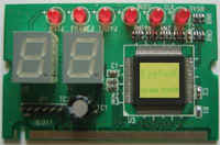
mini-pci 笔记本电脑测试卡 |
| 产品简介:笔记本电脑专用,MINI PCI
插槽,原装卡 300元. 产品大图:
产品详细介绍: Award Software Internationalâ Elite BIOSTM Version 4.51PG POST Codes NOTE: EISA POST codes are typically output to port address 300h. ISA POST codes are output to port address 80h Code (hex) Name Deacxiption C0 Turn off chipset OEM specific-cache control Cache 1 processor Test 1 Processor status (1FLAGS) Verification. Tests the following processor status flags: carry,zero,sign,overflow, The BIOS sets each flag,verifies they are set ,then turns each flag off and verifies it is off. 2 processor Test 2 Read/Write/Verify all cpu registers except ss,sp,andbp with date pattern FF and 00. 3 Initialize Chips Disable NMI, PIE, AIE, UEI ,SQWV Disable Video, parity checking,DMA Reset mach coprocessor Clear all page registers, CMOS shutdown byte Initialize timer 0,1,and 2, including set EISA timer to a known state Initialize DMA controllers 0 and 1. Initialize interrupt controllers 0 and 1 Initialize EISA extended registers. AWARDBIOS 1/8 4 Test Memory RAM must be periodically refreshed to Refresh Toggle keep the memory from decaying.This function ensures that the memory refresh function is working properly. 5 Blank video, keyboard controller initialization. Initialize keyboard 6 Reserved 7 Test Cmos Verifies CMOS is working correctly, Interface and detects bad battery. Battery Status BE Chipset default Programming chipset register with power Initialization on BIOS defaults. C1 Memory presence OEM specific-Test to size on-board test memory C5 Early shadow OEM specific-Early shadow enable for fast boot. C6 Cache presence External cache size detection test 8 Setup low memory Early chip set initialization memory pesence test OEM chip set routines Clear low 64k of memory Test first 64k memory. AWARDBIOS 2/8 9 Early Cache Cyrix CPU initialization Initialization Cache initialization A Setup Interrupt Initialize first 120 interrupt Vector Table vectors with SPURIOUS-INT-HDLR and initialize INT 00h-1Fh according to INT-TBL B Test CMOS RAM Test CMOS RAM Checksum,if bad,or Checksum insert key pressed,load defaults. C Initialize Detect type of keyboard controller keyboard (optional) Set NUM-LOCK status. D Initialize Video Detect CPU clock, Interface Read CMOS location 14h to find out type of video in use. Detect and Initialize Video Adapter. E Test Video Test video memory,write sign-on Memory message to screen, Setup shadow RAM-Enable shadow according to Setup. F Test DMA BIOS checksum test. Controller 0 Keyboard detect and initialization 10 Test DMA Controller 1 11 Test DMA page Test DMA Page registers. registers AWARDBIOS 3/8 12-13 Reserved 14 Test Timer Test 8254 Timer 0 Counter 2. Counter 2 15 Test 8259-1 Verify 8259 channel 1 masked MASK Bits interrupts by alternately turning off and on the interrupt lines. 16 Test 8259-2 Verify 8259 channcl 2 masked MASK bits interrupts by alternately turning off and on the interrupt lines. 17 Test Stuck Turn off interrupsd then verify no 8259 Interrupts interrupt is on. 18 Test 8259 Force an interrupt and verify the Interrupt interrupt occurred. Functionality 19 Test Stuck NMI Verify NMI can be cleared. Bits(Parity/IO Check) 1A Display CPU clock 1B-1E Reserved 1F Set EISA Mode If EISA non-volatile memory checksum is good, execute EISA initialization. If not, execute ISA tests an clear EISA mode flag. Test EISA Configuration Memory integrity (checksum a communication interface). AWARDBIOS 4/8 20 Enable Slot 0 Initialize slot 0 (system board). 21-2F Enable Slots Initialize slots 1 through 15 1-15 30 Size Base and size base memory from 256k to 640k Extended Memory and extended memory above 1MB. 31 Test Base and Test base memory from 256k to 640k Extended Memory and extended memory above 1MB using various patterns. NOTE:This test is skipped in EISA mode and can be skipped with ESC key in ISA mode. 32 Test EISA If EISA Mode flag is set then test Extended Memory EISA memory found in slots initialization. NOTE:This test is skipped in ISA mode and can be skipped with ESC key in EISA mode. 33-3B Reserved 3C Setup Enabled 3D Initialize & Detect if mouse is present, Install Mouse initialize mouse,install interrupt vectors. 3E Setup Cache Initialize cache controller. Controller 3F Reserved AWARDBIOS 5/8 BF Chipset Program chipset registers Initialization with setup values 40 Display virus protect disable or enable 41 Initialize Initialize floppy disk Floppy Drive & controller and any drives. Controller 42 Initialize Hard Initialize hard drive controller and Drive & any drives. Controller 43 Detect & Initialize any serial and parallel Initialize ports(also game port). Serial/Parallel ports 44 Reserved 45 Detect & Initialize math coprocessor. Initialize Math Coprocessor 46 Reserved 47 Reserved 48-4D Reserved AWARDBIOS 6/8 4E Manufacturing Reboot if Manufacturing POST POST Loop or Loop pin is set. Otherwise display Display Messages any messages (i,e., any non-fatal error that were detected during POST) and enter setup. 4F Security Check Ask password security (optional). 50 Write CMOS Write all CMOS values back to RAM and clear screen. 51 Pre-boot Enable Enable parity checker Enable NMI, Enable cache before boot. 52 Initialize Initialize any option ROMs present Option ROMs from C8000h to EFFFFh NOTE:When FSCAN option is enabled,ROMs initialize from C8000h to E7FFFh. 53 Initialize Time Initialize time value in 40h: BIOS value area. 60 Setup Virus Setup virus protect according to Protect Setup. 61 Set Boot Speed Set system speed for boot 62 Setup NumLock Setup NumLock status according to setup. 63 Boot Attempt Set low stack Boot via INT 19h AWARDBIOS 7/8 B0 Spurious If nterrupt occurs in protected B1 Unclaimed NMI If unmasked NMI occurs, display Press F1 to disable F1 NMI, F2 reboot. E1-EF Setup Pages E1- Page 2, etc. FF Boot AWARDBIOS 8/8 AMIBIOS 071596 VERSION 6.24 CHECK POINT LIST ------------------------------------------------------------------------------------ Following is checkpoint list in AMIBIOS in order of execution Check point Description Uncompressed INIT code checkpoints D0 NMI IS Disabled. CPU ID saved. Init code Checksum verification starting. D1 To do DMA init, Keyboard controller BAT test,start memory refresh and going to 4GB flat mode. D3 To start Memory sizing. D4 To comeback to real mode.Execute OEM patch.Set stack. D5 E000 ROM enabled.Init code is copied to segment 0 and control to be transfered to segment 0. D6
Control is in segment 0. To check BIOS checksum.
If either to check point E0 else goto check point D7. D7 To pass control to Interface Module. D8 Main BIOS runtime code is to be decompressed. D9 Control to be passed to main BIOS in shadow RAM. Boot Block Recovery Code Check Points E0 OnBoard Floppy Controller (if any) is initialzed. E1 To star base 512K memory test . E2 To initialize interrupt vector table. E6 To enable floppy and timer IRQ,enable internal cache. ED Initialize floppy drive . EE Start looking for a diskette in drive A: and read lst sector of the diskette. AMIBIOS 1/8 EF Floppy read error. F0 Start searching "AMIBOOT.ROM" file in root directory. F1 "AMIBOOT.ROM" file not present in root directory. F2 Start reading FAT table and analyze FAT to find the cluster occupied by "AMIBOOT.ROM" file. F3 Start reading "AMIDBOOT.ROM" file cluster by cluster. F4 "AMIBOOT.ROM" file not of proper size. F5 Disable internal cache. FB Detect Flash type present. FC Erase Flash. FD Program Flash. FF Flash program successful. BIOS is restart. Runtime code is uncompressed in F000 shadow ram 03 NMI is Disabled.To check soft reset/power-on. 05 BIOS stack set.Going to disable Cache if any. 06 POST code to be uncompressed. 07 CPU init and CPU data area init to be done. 08 CMOS checksum calculation to be done next. 0B Any initialization before Keyboard BAT to be done next. 0C KB controller I/B free. To issue the BAT command to Keyboard controller. 0E Any initialization after KB controller BAT to be done next. 0F Keyboard command byte to be written. 10 Going to issue Pin-23,24 blocking/unblocking command. 11
Going to check pressing of , 12
TO init CMOS if "Init CMOS in every boot
"is set or Pressed.Going to disable DMA and Interrupt controllers. 13 Video display is disabled and port-B is initialized. Chipset init about to start. 14 8254 timer test about to start. 19 About to start memory refresh test. AMIBIOS 2/8 1A Memory Refresh line is toggling.Going to check 15us ON/OFF time. 23 To read 8042 input port and disable Megakey GreenPC feature.Make BIOS code segment writeable. 24 To do any setup before Int vector init. 25 Interrupt vector initialization about to being. TO clear password if necessary. 27 Any initialization before setting video mode to be done. 28 Going for monochrome mode and color mode setting. 2A Different BUSes init (system,static,output devices)to start if present. 2B To give control for any setup required before optional video ROM check. 2C To look for optional video ROM and give control. 2D TO give control to do any processing after video ROM returns control. 2E If EGA/VGA not found then do Dissplay memory R/W test. 2F EGA/VGA not found.Display memory R/W test about to begin. 30 Display memory R/W test passed. About to look for the retrace checking. 31 Display memory R/W test or retrace checking failed.To do alternate Display memory R/W test. 32 Alternate Display memory R/W test passed.To look for the alternate display retrace checking. 34 Video display checking over.Display mode to be set next. 37 Display mode set.Going to display the power on message. 38 Different BUSes init(input,IPL,general devices) to start if pressent. (please see Appendix for details of different BUSes). 39 Display different BUSes initialization error messages. (Please see Appendix for details of different BUSes). 3A
New cursor position read and saved.To display the
Hit 40 To prepare the descriptor tables. 42 To enter in virtual mode for memory test. 43 To enable interrupts for diagnostics mode. 44 To initialized data to check memory wrap around at 0:0. 45 Data initialized Going to check for memory wrap around at 0:0. and finding the total system memory size. AMIBIOS 3/8 46 Memory wrap around test done.Memory size calculation over. About to go for writing patterns to test memory. 47 Patterns to be tested written in extended memory. Going to write patterns in base 640K memory. 48 Patterns written in base memory. Going to findout amount of memory bolow 1M memory. 49 Amount of memory below 1M found and verified. Going to findout amount of memory above 1M memory. 4B Amount of memory above 1M found and verified. Check for soft reset and going to clear memory below 1M for soft reset. (If power on, go to check point#4Eh) 4C Memory below 1M cleared. (SOFT RESET) Going to clear memory above 1M . 4D Memory above 1M cleared. (SOFT RESET) Going to save the memory size.(Goto check point#52h). 4E Memory test started. (NOT SOFT RESET) About to display the first 64K memory size. 4F Memory size display started .This will be updated during memory test. Going for sequential and random memory test. 50 Memory testing/initialization below 1M complete. Going to adjust displayed memory size for relocation/shadow. 51 Memory size display adjusted due to relocation/shadow. Memory test above 1M to follow. 52 Memory testing/initialization above 1M complete. Going to save memoryy size information. 53 Memory size information is saved. CPU registers are saved. Going to enter in real mode. 54 Shutdown successful,CPU in real mode. Going to disable gate A20 line and disable parity/NMI. 57 A20 address line, parity/NMI disable successful. Going to adjust memory size depending on relocation/shadow. 58 Memory size adjusted for relocation/shadow.
Going to clear Hit AMIBIOS 4/8 59
Hit About to start DMA and interrupt controller test. 60 DMA page register test passed. To do DMA#1 base register test. 62 DMA#1 base register test passed. To do DMA#2 base register test. 65 DMA#2 base register test passed. To program DMA unit 1 and 2 . 66 DMA unit 1 and 2 programming over. To initialize 8259 interrupt controller. 7F Extended NMI sources enabling is Progress. 80 Keyboard test started.clearing output buffer,checking for stuck key, to issue keyboard reset command. 81 Keyboard reset error/stuck key found. To issue keyboard controller interface test command. 82 Keyboard controller interface test over. To write command byte and init circular buffer. 83 Command byte written,Global data init done. To check for Lock-key. 84 Lock-key checking over. To check for memory size mismatch with CMOS. 85 Memory size check done.To display soft error and check for password or bypass setup. 86 Password checked.About to do programming before setup. 87 Programming before setup complete. To uncompress SETUP code and execute CMOS setup. 88 Returned from CMOS setup program and screen is cleared. About to do programming after setup. 89 Programming after setup complet. Going to display power on screen message. 8B
First screen message dispalyed. PS/2 Mouse check and extended BIOS data area allocation to be done. 8C Setup options programming after CMOS setup about to start. 8D Going to hard disk controller reset. 8F Hard disk controller reset done. floppy setup to be done next. 91 Floppy setup complet.Hard disk setup to be done next. 95 Init of different BUSes optional ROMs from C800 to start. 96 Going to do any init before C800 optional ROM control. AMIBIOS 5/8 97 Any Init before C800 optional ROM control is over. Optional ROM check and control will be done next. 98 Optional ROM control is done. About to give control to do any required processeing after optional ROM returns control and enable external cache. 99 Any initialization required after optional ROM test over. Going to setup timer data area and printer base address. 9A Return after setting timer data area and printer base address. Going to set the RS-232 base address. 9B Return after RS-232 base address. Going to do any initialization before Coprocceor is over. 9C Required initialization before Coprocessor is over. Going to initialize the Coprocessor next. 9D Coprocesor initialized. Going to do any initialization after Coprocessort test. 9E Initialization after Coprocessor test is complete.Going to check extd Keyboard,kaeyboard ID and num-lock.Keyboard ID command to be. A2 Going to display any soft errors. A3 Soft error display complete.Going to set Keyboard typematic rate. A4 Keyboard typematic rate set.To program memory WAIT STATES. A5 Going to enable parity/NMI. A7 NMI and parity enabled. Going to do any initalization required before giving control to optional ROM at E000. A8 Initialization before E000 ROM control over. A9 Returned from E000 ROM control. Going to do any initialization required after E000 optional ROM control is over. AA Initialization after E000 optional ROM control is over. Going to display the system configuration. AB TO build MP table if needed. AC TO uncompress DMI data and execute DMI POST init. B0 System configuration is displayed. B1 Going to copy any code to specific area. 00 Copying of code to specific area done. Going to give control to INT-19 boot loader. AMIBIOS 6/8 AMIBIOS 071596 Version 6.24 Check Point List -------------------------------------------------------------------------- APPENDIX The system BIOS gives control to the different BUSes at checkpoints to do various tasks on the different BUSes. CHECK-POINT DESCRIPTION OF CHECK-POINT 2A Different BUSes init(system,start,output devices)to start if present. 38 Different BUSes init(input,IPL,general devices)to start if present. 39 Display different BUSes initialization error messages. 95 Init of different BUSes optional ROMs from C800 to start. AMIBIOS 7/8 While control is inside the different BUS routines,checkpoints are output to port 80h as WORD to identify the routines under execution. These are WORD checkpoints,the LOW BYTE of checkpoint is the system BIOS checkpoint from where the control is passed to the different BUS routines and the HIGH BYTE of checkpoint is the indication of which routine is being executed in differ- ent BUSes. The details of HIGH BYTE of these checkpoints are as follows: HIGH BYTE XY the upper nibble "x" indicates the funtion#is being executed. "x" can 0 to 7. 0=func#0,disable all devices on the BUS concerned. 1=func#1,static devices init on the BUS concerned. 2=func#2,output device init on the BUS concerned. 3=func#3,input device init on the BUS concerned. 4=func#4,IPL device init on the BUS concerned. 5=func#5,general device init on the BUS concerned. 6=func#6,error reporting for the BUS concerned. 7=func#7,add-on ROM init for all BUSes. the lower nibble "Y" indicates the BUS on which the different routines are being executed. "Y" can be from 0 to 5. 0=Generic DIM (Device initialization Manager). 1=On-board System devices. 2=ISA devices. 3=EISA devices. 4=ISA PnP devices. 5=PCI devices. AMIBIOS 8/8 PhoenixBIOS 4.0 Release 6.0 POST Tasks and Beep Codes When you turn on or reset an IBM-compatible PC,the BIOS first performs a number of tasks,called the Power-on-Self-Test(POST).These tasks test and initialize the hardware and then boot the Operating System from the hard disk. At the beginning of each POST task,the BIOS outputs the test-point error code to I/O port 80h.Programmers and technicians use this code during trouble shooting to establish at what point the system failed and what routine was being performed.Some motherboards are equipped with a seven segment LED display that displays the current value of port 80h.For production boards which do not contain the LED display,you can purchase an installable"Port 80h" card that performs the same function. If the BIOS detects a terminal error condition,it issues a terminal-error beep code(See following),attempts to display the error code on upper left corner of the screen and on the port 80h LED display,and halts POST.It attempts repeatedly to write the error to the screen.This attempt may "hash" some CGA displays. If the system hangs before the BIOS can process the error,the value displayed at the port 80h is the last test performed. In this case, the screen does not display the error code. Terminal POST Errors There are several POST routines that require success to finish POST.If they fail,they issue a POST Terminal Error and shut down the system.Before shutting down the error system, the error handler issues a beep code signifying the test point error,writes the error to port 80h,attempts to initialize the video, and writes the error in the upper lift corner of the screen(using both mono and colot adapters). PHOENIXBIOS 1/7 The routine derives the beep code form the test point error as follows: 1. The 8-bit error code is broken down to four 2-bit groups. 2. Each group is made one-based(1 through 4)by adding 1. e. Short beeps are generated for the number in each group. Example: Testpoint 16h=00 01 01 10=1-2-2-3 beeps POST Task Routines The following is a list of the Test Point codes written to port 80h at the start of each routine,the beep codes issued for terminal errors,and a description of the POST routine. Unless otherwise noted, these codes are valid for PhoneixBIOS 4.0 Release 6.0. NOTE:The following routines are sorted by their test point numbers assigned in the BIOS code. Their actual order as executed during POST can be quite different. Code Beeps POST Routine Description 02h Verify Real Mode 03h Disable Non-Maskable Interrupt(NMI) 04h Get CPU type 06h Initialize system hardware 08h Initialize chipset with initial POST values 09h Set IN POST flag 0Ah Initialize CPU registers 0Bh ENABLE CPU cache 0Ch Initialize caches to initial POST values 0Eh Initialize I/O component 0Fh Initialize the local bus IDE 10h Initialize Power Management 11h Load alternate registers with initial POST values 12h Restort CPU control word during warm boot 13h Initialize PCI Bus Mastering devices PHOENIXBIOS 2/7 Code Beeps POST Routine Description 14h Initialize keyboard controller 16h 1-2-2-3 BIOS ROM checksum 17h Initialize cache before memory autosize 18h 8254 timer initialization 1Ah 8237 DMA controller initialization 1Ch Reset Programmable Interrupt Controller 20h 1-3-1-1 Test DRAM refresh 22h 1-3-1-3 Test 8742 keyboard Controller 24h Set ES segment register to 4 GB 26h Enable A20 line 28h Autosize DRAM 29h Initialize POST Memory Manager 2Ah Clear 512 KB base RAM 2Ch 1-3-4-1 RAM failure on address line xxxx* 2Eh 1-3-4-3 RAM failure on data bits xxxx* of low byte of memory bus 2Fh Enable cache before system BIOS shadow 30h 1-4-1-1 RAM failure on data bits xxxx* of high byte pf memory bus 32h Test CPU bus-clock frequency 33h Initialize Phonenix Dispatch Manager 36h Warm start shut down 38h Shadow system BIOS ROM 3Ah Autosize cache 3Ch Advanced configuration of chipset registers 3Dh Load alternate registers with CMOS values 42h Initialize interrupt vectors 45h POST device initialization 46h 2-1-2-3 Check ROM copyright notice 48h Check video configuration against CMOS 49h Initialize PCI bus and devices 4Ah Initialize all video adapters in system 4Bh QuietBoot start (optional) 4Ch Shadow video BIOS ROM PHOENIXBIOS 3/7 Code Beeps POST Routine Description 4Eh Display BIOS copyright notice 50h Display CPU type and speed 51h Initialize EISA board 52h Test keyboard 54h Set key click if enabled 58h 2-2-3-1 Test for unexpected interrupts 59h Initialize POST display service 5Ah Display prompt "Press F2 to enter SETUP" 5Bh Disable CPU cache 5Ch Test RAM between 512 and 640 KB 60h Test extended memory 62h Test extend memory address lines 64h Jump to UserPatch1 66h Configure advanced cache registers 67h Initialize Multi Processor APIC 68h Enable external and CPU caches 69h Setup System Management Mode (SMM)area 6Ah Displsy external L2 cache size 6BH Load custom defaults (optional) 6Ch display shadow-area message 6Eh Display possible high address for UMB recovery 70h Display error messages 72h Check for configuration errors 76h Check for keyboard errors 7Ch Set up hardware interrupt vectors 7Eh Initialize coprocessor if present 80h Disable onboard Super I/O ports and IRQs 81h Late POST device initialization 82h Detect and install external RS232 ports 83h Configure non-MCD IDE controllers 84h Detect and install external parallel ports 85h Initialize PC-compatible PnP ISA devices 86h Re-initialize onboard I/O ports . PHOENIXBIOS 4/7 Code Beeps POST Routine Description 87h Configure Motheboard Configurable Devices(optional) 88h Initialize BIOS Data Area 89h Enable Non-Maskable Interrupts(NMIs) 8Ah Initialize BIOS Data Area 8Bh Test and initialize PS/2 mouse 8Ch Initialize floppy controller 8Fh Determine number of ATA drives (optional) 90h Initialize hard-disk controllers 91h Initialize local-bus hard-disk controllers 92h Jump to UserPatch2 93h Build MPTABLE multi-processor boards 95h Install CD ROM for boot 96h Clear huge ES segment register 97h Fixup Multi Processor table 98h 1-2 Search for option ROMs.One long,two short beeps on checksum failure 99h Check for SMART Drive (optional) 9Ah Shadow option ROMs 9Ch Set up Power Management 9Dh Initialize security engine (optional) 9Eh Enable hardware interrupts 9Fh Determine number of ATA and SCSI drives A0h Set time of day A2h Check key lock A4h Initialize Typematic rate A8h Erase F2 prompt AAH Scan for F2 key stroke ACh Enter SETUP AEh Clear Boot flag B0h Check for errors B2h POST done-prepare to boot operating system B4h 1 One short beep before boot B5h Terminate QuietBoot(optional) PHOENIXBIOS 5/7 Code Beeps POST Routine Description B6h Check password (optional) B9h Prepare Boot BAh Initialize DMI parameters BBh Initialize PnP Option ROMs BCh Clear parity checkers BDh Display MultiBoot menu BEh Clear screen (optional) BFh Check virus and backup reminders C0h Try to boot with INT 19 C1h Initialize POST Error Manager(PEM) C2h Initialize error logging C3H Initialize error display function C4h Initialize system error handler C5h PnPnd dual CMOS (optional) C6h Initialize notebook docking(optional) C7h Initialize notebook docking late C8h Force check (optional) C9h Extended checksum(optional) D2h Unknown interrupt E0h Initialize the chipset E1h Initialize the bridge E2h Initialize the CPU E3h Initialize system timer E4h Initialize system I/O E5h Check force recovery boot E6h Checksum BIOS ROM E7h Go to BIOS E8h Set Huge Segment E9h Initialize Multi Precessor EAh Initialize OEM special code EBh Initialize PIC and DMA ECh Initialize Memory type EDh Initialize Memory size PHOENIXBIOS 6/7 Code Beeps POST Routine Description EEh Shadow Boot Block F0h System memory test F1h Initialize Run Time Clock F2h Initialize video F3h Initialize System Management Mode F4h 1 Output one beep before boot F5h Boot to Mini DOS F6h Clear Huge Segment F7h Boot to Full DOS Continued.... If the BIOS detects error 2C,2E,or 30 (base 512K RAM error),it displays an additional word-bitmap (xxxx)indicating the address line or bits that failed.For example,"2C 0002" means address line 1 (bit one set)has failed. "2E 1020" means data bits 12 and 5 (bits 12 and 5 set)have failed in the lower 16 bits. Note that error 30 cannot occur on 386SX systems because they have a 16 rather than 32-bit bus. The BIOS also sends the bitmap to the port-80 LED display. It first displays the check point code,followed by a delay,the high-order byte,another delay,and then the low-order byte of the error. It repeats this sequence continuously . PHOENIXBIOS 7/7
|